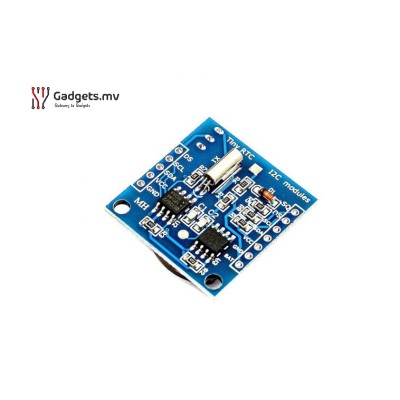
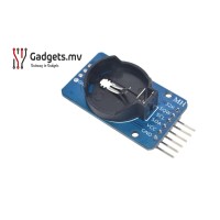
Real Time Clock Module DS1307
Real-time clocks (RTC), as the name recommends are clock modules. The DS1307 real-time clock (RTC) IC is an 8 pin device using an I2C interface. The DS1307 is a low-power clock/calendar with 56 bytes of battery backup SRAM. The clock/calendar provides seconds, minutes, hours, day, date, month and year qualified data. The end date of each month is automatically adjusted, especially for months with less than 31 days.
They are available as integrated circuits (ICs) and supervise timing like a clock and also operate dates like a calendar. The main advantage of RTC is that they have an arrangement of battery backup which keeps the clock/calendar running even if there is a power failure. An exceptionally little current is required for keeping the RTC animated. We can find these RTCs in many applications like embedded systems and computer motherboards, etc.
Features
Real-time clock (RTC) counts seconds, minutes, hours, date of the month, month, day of the week, and year with leap-year compensation valid up to 2100
Chip: DS1307
Memory Storage: 24C32 32KB I2C EEPROM
56 Bytes of Non-volatile memory available to the use
Programmable Square-Wave Output Signal
Input Voltage: 5V
Frequency: 32.768KHz
Interface: I2C
Operating Temperature: -40℃ ~ +85℃
Size: 27mm x 28mm x 8.4mm
Pin Description of DS1307:
Pin 1, 2: Connections for standard 32.768 kHz quartz crystal. The internal oscillator circuitry is intended for operation with a crystal having a specified load capacitance of 12.5pF. X1 is the input to the oscillator and can alternatively be connected to an external 32.768 kHz oscillator. The output of the internal oscillator, X2 is drifted if an external oscillator is connected to X1.
Pin 3: Battery input for any standard 3V lithium cell or another energy source. Battery voltage should be between 2V and 3.5V for suitable operation. The nominal write protects trip point voltage at which access to the RTC and user RAM is denied is set by the internal circuitry as 1.25 x VBAT nominal. A lithium battery with 48mAhr or greater will backup the DS1307 for more than 10 years in the absence of power at 25ºC. UL recognized to ensure against reverse charging current when utilized as a part of conjunction with a lithium battery.
Pin 4: Ground.
Pin 5: Serial data input/output. The input/output for the I2C serial interface is the SDA, which is the open drain and requires a pull-up resistor, allowing a pull-up voltage to 5.5V. Regardless of the voltage on VCC.
Pin 6: Serial clock input. It is the I2C interface clock input and is used in data synchronization.
Pin 7: Square wave/output driver. When enabled, the SQWE bit set to 1, the SQW/OUT pin outputs one of four square-wave frequencies (1Hz, 4 kHz, 8 kHz, and 32 kHz). This is also an open drain and requires an external pull-up resistor. It requires the application of either Vcc or Vb at to operate SQW/OUT, with an allowable pull-up voltage of 5.5V and can be left floating, if not used.
Pin 8: Primary power supply. When the voltage is applied within normal limits, the device is fully accessible and data can be written and read. When a backup supply is connected to the device and VCC is below VTP, read and writes are inhibited. However, at low voltages, the timekeeping function still functions.
NOTE: Doesn't include battery.
Related Products
Real Time Clock Module DS1302
The DS1302 is an accurate clock module which contains a real-time clock/calendar and 31 bytes of sta..
MVR 30.00
Real Time Clock Module DS3231
DS3231 is a low-cost, extremely accurate I2C real-time clock (RTC), with an integrated temperature-c..
MVR 50.00
Tags: RTC, Real Time Clock, DS1307 real, time, clock, module, ds1307, rtc


